PROJECT_04

Control de Acceso Físico
Access control for a school, with a board made at home: the backend decides who gets in, not the reader.
- TYPE
- Hardware · Full Stack
- STATUS
- IN PRODUCTION
- DIAGRAMS
- 4
- SCREENSHOTS
- 13
01 What it is
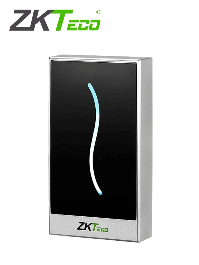
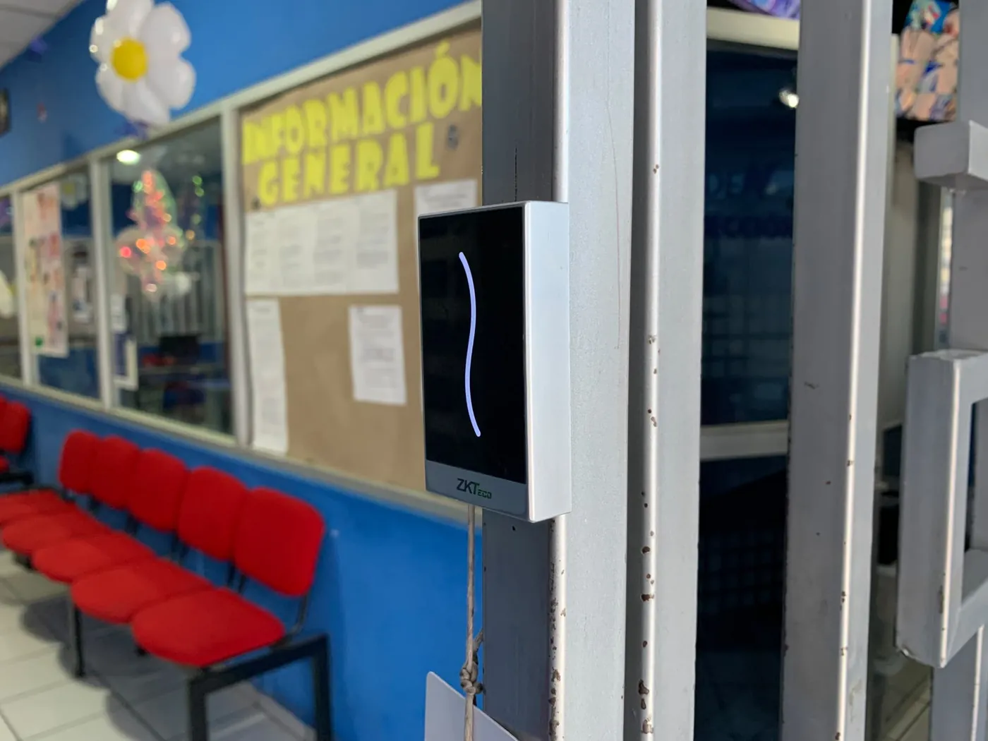
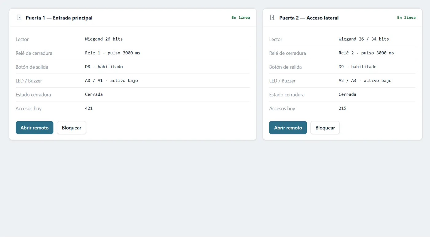
Access control for a school, end to end: a custom PCB with an Arduino Nano driving two Wiegand readers and two locks, a ZKTeco PROID10BM MIFARE card reader on each door, a Spring Boot backend that decides who gets in and a web panel to add, remove and block students, hosted on the school own server.
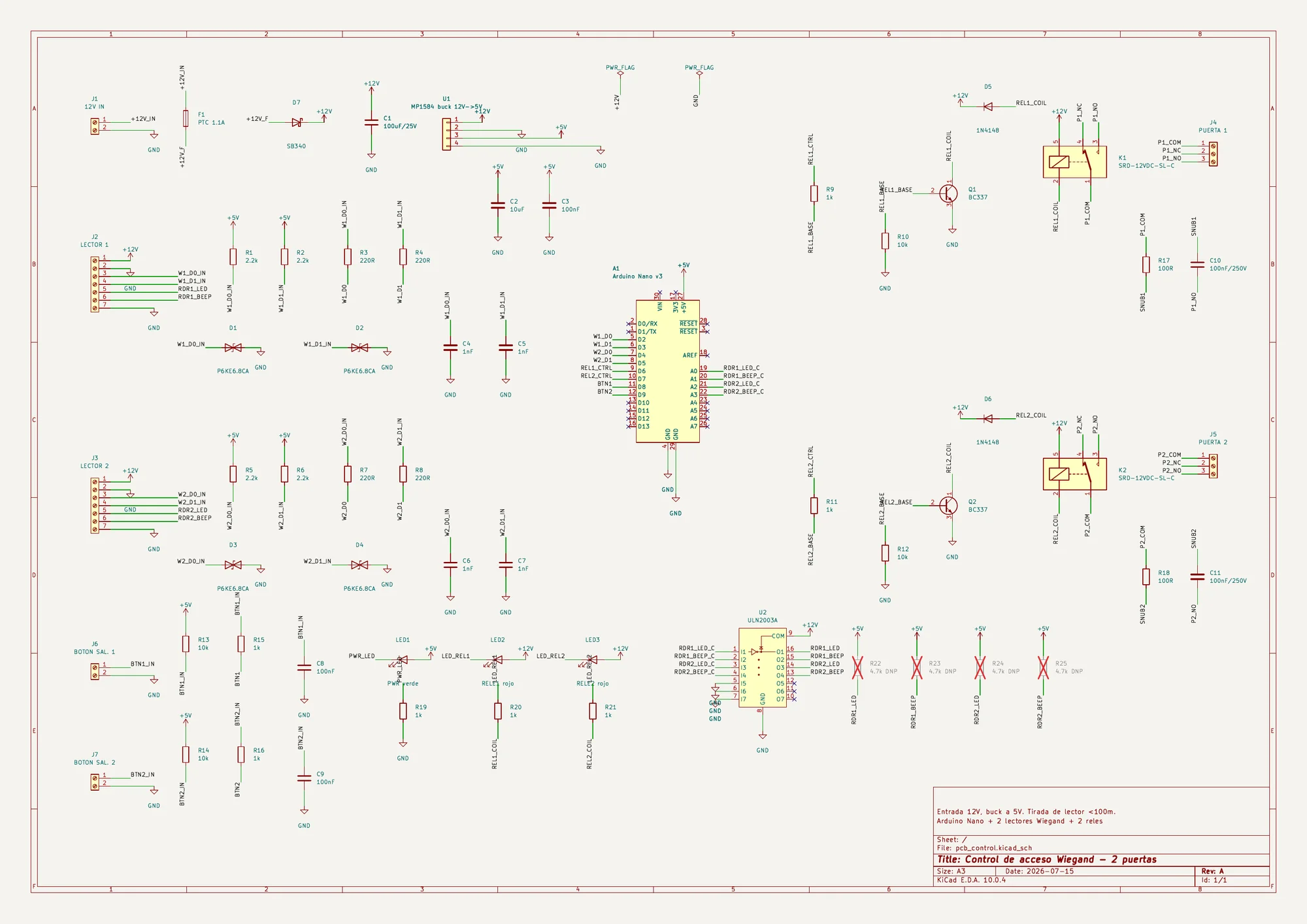
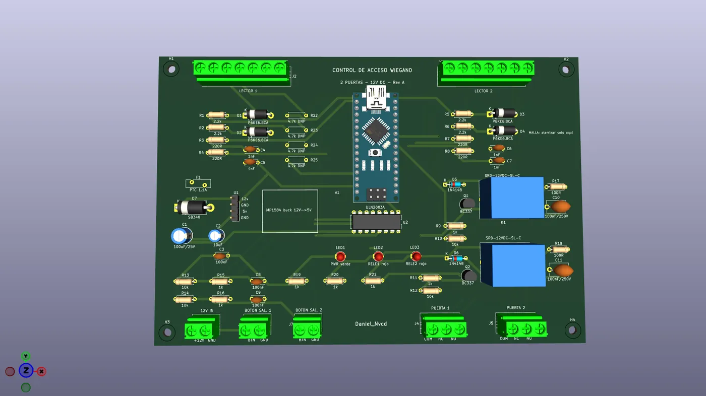
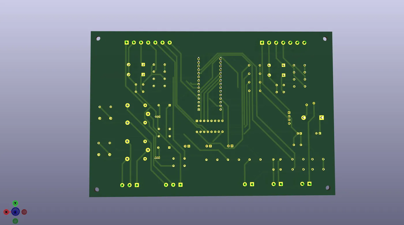
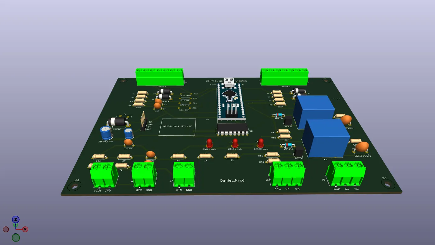
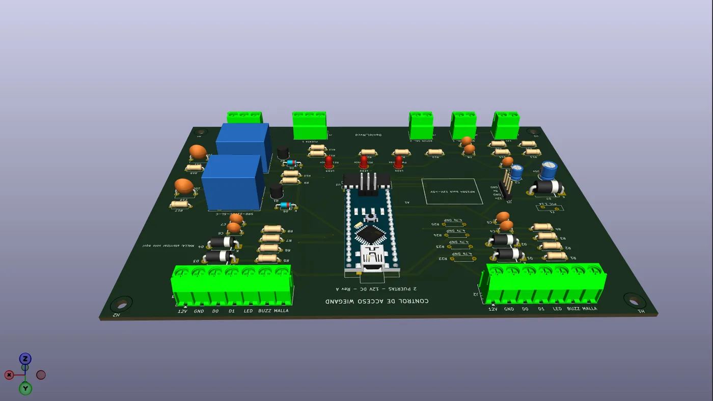
pcb_controlboard Rev A: 170 × 115 mm, 61 through-hole components, 42 nets, ERC and DRC at zero.- Two independent Wiegand 26/34 readers, two door relays as dry contacts and two exit buttons.
- The board decides nothing: it reads the card, sends the ID over serial and opens only when the backend gives the signal.
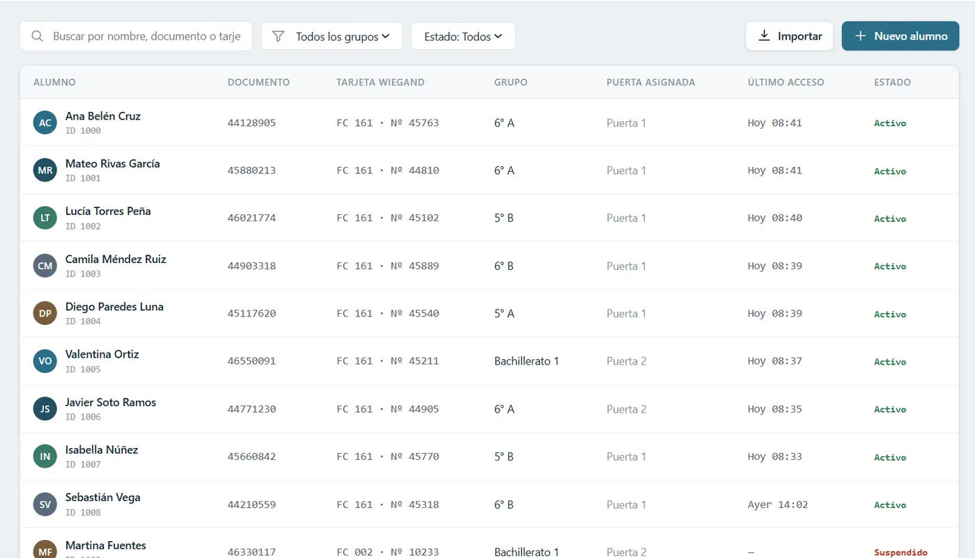
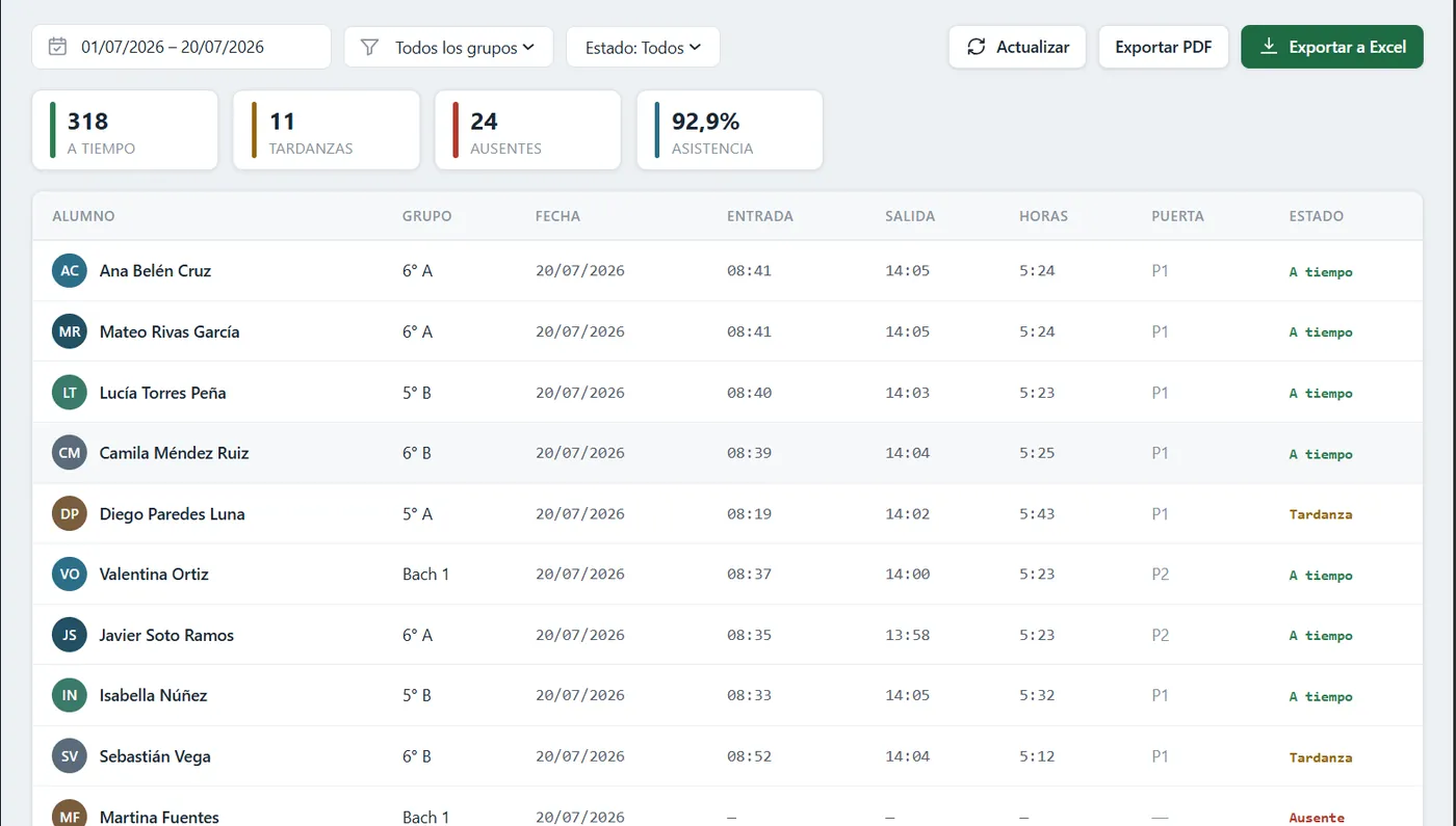
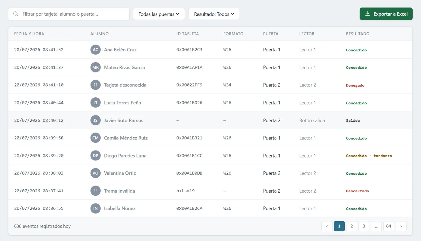
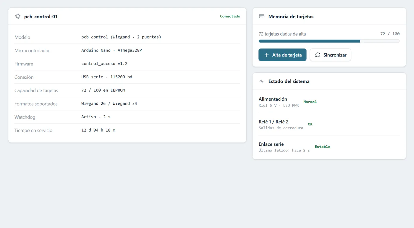
- Spring Boot backend that checks whether the student is active or blocked, and a web panel with students, cards, access history and status.
02 The board · Rev A
Designed in KiCad. Everything is through-hole on purpose: no SMD, so the whole board solders with one technique and one iron. Four M3 screws in 3.2 mm holes.
| Block | Parts | What for |
|---|---|---|
| Brain | Arduino Nano v3 (A1) | Reads both readers on interrupt and drives relays, buttons, LED and buzzer |
| Power | PTC F1 1.1 A · SB340 Schottky D7 · MP1584 buck U1 · C1 100 µF · C2 10 µF | Protected 12 V; 5 V for the Nano and the pull-ups |
| Wiegand input ×2 | P6KE6.8CA TVS D1–D4 · C4–C7 1 nF · R3, R4, R7, R8 220 Ω · pull-ups R1, R2, R5, R6 2.2 kΩ | Protects the AVR and buys cable length |
| Relays ×2 | SRD-12VDC-SL-C K1, K2 · BC337 Q1, Q2 · 1N4148 D5, D6 · snubber R17, R18 100 Ω + C10, C11 100 nF/250 V | COM/NC/NO dry contact to the lock |
| Reader feedback | ULN2003A U2 · unpopulated R22–R25 4.7 kΩ pull-ups | LED and buzzer of both readers with a single IC |
| Indicators | Green LED1 (PWR) · red LED2, LED3 (relay 1 and 2) | None of them costs a Nano pin |
| Terminal blocks | MX126/DG126 5.00 mm pitch: J2, J3 7-way · J4, J5 3-way · J1, J6, J7 2-way | Readers, doors, 12 V input and exit buttons |
03 How it works
Power
12 V comes in through J1, through the PTC F1 (resettable: it recovers on its own once the fault is gone) and the Schottky D7, which blocks reverse polarity. That rail directly feeds the relay coils, both readers and the input of the U1 buck, which steps down to 5 V for the Nano and the pull-ups: about 40 mA in total.
Reading Wiegand
The reader D0 and D1 lines are open collector: at rest both sit at 5 V through the 2.2 kΩ pull-ups. To send a bit, the reader pulls one to ground for ~50 µs; a pulse on D0 = bit 0, a pulse on D1 = bit 1. A 26-bit card is 26 pulses spread across the two lines.
Every line runs TVS → 1 nF filter → 220 Ω series resistor → Nano pin. That chain is what buys distance: Wiegand is not differential and that is why it is sensitive to noise.
Opening and output
When the backend authorizes, the Nano drives D6 high, R9 pushes ~4.3 mA into the base of Q1, the transistor saturates and connects the coil negative to ground. R10 (10 kΩ) keeps the base grounded while the Nano boots: without it the pin floats and the relay could fire on its own at power-up. D5 absorbs the coil reverse spike.
J4 and J5 deliver COM/NC/NO as a dry contact: the relay is just a switch and the lock current never goes through the board. The RC snubber (R17 + C10) bridges COM–NO so the arc does not weld the contacts; RC was chosen over a diode because it has no polarity and works the same with DC or AC loads.
Board LEDs, reader LED and buzzer
Three LEDs and none costs a Nano pin. LED1 (green, PWR) hangs off the 5 V rail: if it lights, the buck works. LED2 and LED3 (red) go from +12 V to the relay coil through R20 and R21: they light exactly when the transistor saturates, so they report the real actuation rather than what the firmware believes. If the relay LED lights and the door does not open, the problem is from the relay outwards; if it does not light, from the transistor inwards. It splits the diagnosis in two.
The reader LED and buzzer are open collector: they must be pulled to ground. Instead of four transistors with their resistors there is a ULN2003A (U2), which brings seven drivers with base resistors and clamp diodes built in; four channels are used. The Nano drives them through A0–A3 and not D10–D13 for a concrete reason: D13 carries the Nano on-board LED and the bootloader blinks it on every boot, so the reader would beep on every reset.
04 Terminal blocks
MX126 / DG126 family, 5.00 mm pitch, 1.3 mm drill and Ø2.8 mm pad. J2 and J3 are rotated 180° so the cable mouth faces the edge, which puts pin 1 on the right: the silkscreen is labelled pad by pad and reads SHIELD · BUZZ · LED · D1 · D0 · GND · 12V left to right. Trust the silkscreen, not the pin number.
| Block | Use | Pins |
|---|---|---|
J2 / J3 | Reader 1 and 2 · 7-way | 12V · GND · D0 · D1 · LED · BUZZ · SHIELD |
J4 / J5 | Door 1 and 2 · dry contact · 3-way | COM · NC · NO |
J1 | 12 V input · 2-way | +12V · GND |
J6 / J7 | Exit button 1 and 2 · 2-way | BTN · GND |
05 Nano pinout
The Nano has only two hardware interrupts and four Wiegand lines are needed here. Reader 1 takes INT0/INT1; reader 2 goes through a pin-change interrupt. That is why the firmware cannot be the basic two-line example.
| Pin | Function | Net | Note |
|---|---|---|---|
D2 · D3 | Reader 1 · D0 / D1 | W1_D0 · W1_D1 | INT0 / INT1, hardware |
D4 · D5 | Reader 2 · D0 / D1 | W2_D0 · W2_D1 | PCINT20 / PCINT21 |
D6 · D7 | Relay 1 / 2 | REL1_CTRL · REL2_CTRL | high = open |
D8 · D9 | Exit button 1 / 2 | BTN1 · BTN2 | low = pressed |
A0 · A1 | Reader 1 LED / buzzer | RDR1_LED_C · RDR1_BEEP_C | → ULN2003A I1 / I2 |
A2 · A3 | Reader 2 LED / buzzer | RDR2_LED_C · RDR2_BEEP_C | → ULN2003A I3 / I4 |
+5V | 5 V input | +5V | from the buck; the Nano USB goes to the server and its Schottky keeps it from being back-fed |
VIN | Not connected | — | on purpose: fed through the 5 V pin |
D10–D13 and A4–A7 remain free: room for door sensors, an RTC or storing cards over I²C.
06 Firmware
control_acceso.ino compiles for arduino:avr:nano with no warnings: 6.5 KB of flash (21 %) and 324 B of RAM. It reads both readers on interrupt and assembles the frame bit by bit; closes the read after 25 ms of silence; accepts 26 and 34 bits and validates both parity bits before sending anything. It stores no cards: the ID goes out over the Nano USB, as a 115200 serial port, to the school server, and the backend decides.
- Sends
CARDwith the reader number and the ID; if the backend answersOPEN, it opens the relay for 3 s without blocking the loop, with a long beep and green LED; onDENYor a bad frame, three short beeps. - Exit buttons with 30 ms debounce.
- The ID is
(facility << 16) | number, the same for Wiegand 26 and 34: both formats collapse to the same 32-bit ID, which is what the server stores when the student is registered. - The backend records every read, authorized or not, in the access history.
- The
PCINT2vector covers the whole port D, so the routine compares against the previous state to keep only the falling edges ofPD4andPD5.
> CARD 1 00A1B2C3    # Nano → backend: lector 1 leyó este ID
> OPEN 1             # backend → Nano: alumno activo, abre el relé 1 tres segundos
> DENY 1             # backend → Nano: bloqueado o desconocido, tres pitidos
> BTN 2              # Nano → backend: botón de salida 2, solo para el historial
07 Resilience
An access controller lives inside a box, with nobody watching it, and has to keep working. These are the decisions made with that in mind, not for elegance.
| If… | Then |
|---|---|
| the firmware hangs | A 2 s watchdog resets the Nano, and the first thing setup() does is drop both relays: if the reset happened with a door open, it does not stay open |
| the reader is not 26-bit | Wiegand 26 and 34 are accepted with their parities; the bit register is 64 bits because a 34-bit frame does not fit in 32 |
| there is noise on the cable | A frame that is not exactly 26 or 34 bits discards itself; the counter keeps climbing past the limit so a burst ends up with an impossible n instead of looking like a card |
| the backend does not answer or the USB is unplugged | The board stays powered by the buck, not by USB. The door does not open: no OPEN, no opening, and the attempt ends in three beeps. Exit buttons keep working because they are local to the board |
| a student must be registered or blocked | Done in the panel, without touching the board: the card ID is captured by presenting it at the reader and the change applies on the next read |
| the board has been on for 49 days | millis() overflows; every wait uses unsigned subtraction, which survives the overflow, and there is not a single delay(): relays, LEDs and beeps are state machines |
08 Verification and risks
What was checked and what was not, kept apart on purpose. A passing ERC does not mean the circuit works: during the design, a serious mistake (BC337 base and collector swapped) survived a perfectly clean ERC. It only showed up when reading the netlist net by net and asking KiCad for the real pin order of the transistor.
| Verified | How |
|---|---|
| ERC: 0 errors, 0 warnings | Schematic electrical rules with --severity-all |
| Netlist: 42 nets | Exported and read net by net: base on Q1.2, collector on Q1.1, coil on K1.2, common on K1.1 |
| Footprints: 61 of 61 | Every footprint checked against its real .kicad_mod, pin to pad |
| DRC: 0 violations | Board design rules |
| Reader LED and buzzer polarity | Against HID documentation, the industry reference: active low, 0–12 V / 100 mA, within ULN2003A spec |
DIAGRAMS
SCREENSHOTS